Deadboxhero wrote: ↑Mon Aug 18, 2025 8:44 pm
Strong work.
Excellent creativity, a rudimentary test that can show differences between conditions with house hold items
@sal this is what we need.
We'll call it the "Mage" Test.
Yes, we see scatter but it could be smoothed out with more tests. 3 tests is the absolute bare minimum for us to see separation between the conditions I would recommend at least 5 in the future.
Especially if dealing with conditions that may have an unknown outcome or counter intuitive behavior.
If the objective was to quantify the difference better that would benefit from more control ( jig sharpening, test fixtures, etc) which would result in more distinct, cleaner data.
The testing shows the behavior that a traditional microbevel with thicker angles at the apex takes more force to cut with than no microbevel.
Hence, why I don't enjoy or use them (as previously shared)
The test is simple enough for others to replicate to compare other behaviors as well.
Mage, well done.
If the edge is a ghost, you are definitely a "Ghostbuster"
Mage7 wrote: ↑Mon Aug 18, 2025 4:53 pm
Deadboxhero wrote: ↑Sun Aug 17, 2025 4:32 pm
Mage7 wrote: ↑Sun Aug 17, 2025 4:15 pm
Sweet! I've been wondering about that for a long time. Thanks for confirmation.
Again, thanks for confirmation that they were measured with a goniometer
I suppose my real question is
how much it matter though.
Applying the regression formula you developed to Rex45 (2.5% MC and 5.3% M6C) and assuming it's 66 HRC, I get the following TCC estimates:
-157 + 15.8*66 – 17.8*30 + 26.2*2.5 + 9.5*5.3 = 467.65
-157 + 15.8*66 – 17.8*50 + 26.2*2.5 + 9.5*5.3 = 111.65
There's a huge decrease in edge retention going from 30 degrees to 50 degrees, but is it optimistic to assume that the decrease wouldn't be as bad if the 50 degree edge in question is formed by extremely small micro-bevels on top of a 30 degree edge?
I'm wondering if that's even something that can be speculated on, or if it would require actual testing to see. If the latter, have you ever thought about doing another set of CATRA tests with micro-bevels?
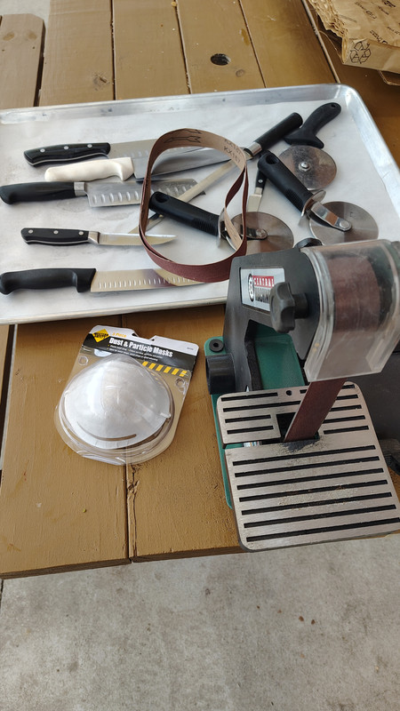
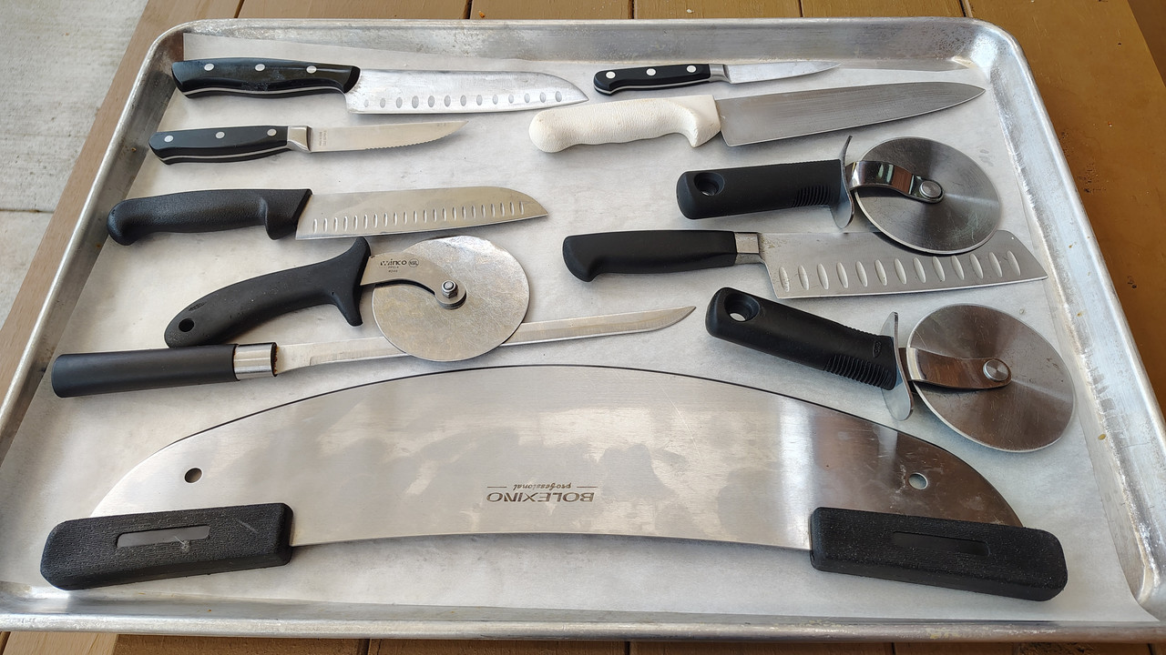
Do a rudimentary test.
Set up a scale on a cutting board and test the weight needed to cut various media with your two different conditions.
In my experience, microbevel performance behaves more like the geometry at the microbevel rather than the back bevel.
This is undesirable, like pre-dulling; reduced bite and cutting longevity.
Here's an idea for a test using Q-tips with the heads cut off. They're a plastic variety with a hollow center, and when they're cut they shoot off in either direction so it makes a pretty clear indication of the moment they're entirely severed. Their diameter is also no larger than the height of my edge bevel, and they compress, so it isolates the forces being measured to the blade grind.
This way I can also record it and measure the readout the very moment that the Q-tip's handle is completely split.
Screenshot_20250818-124748~2.png
Screenshot_20250818-124807~2.png
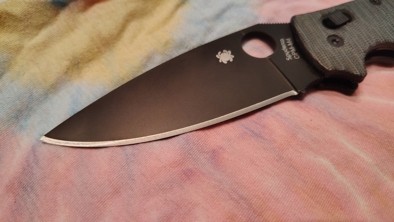
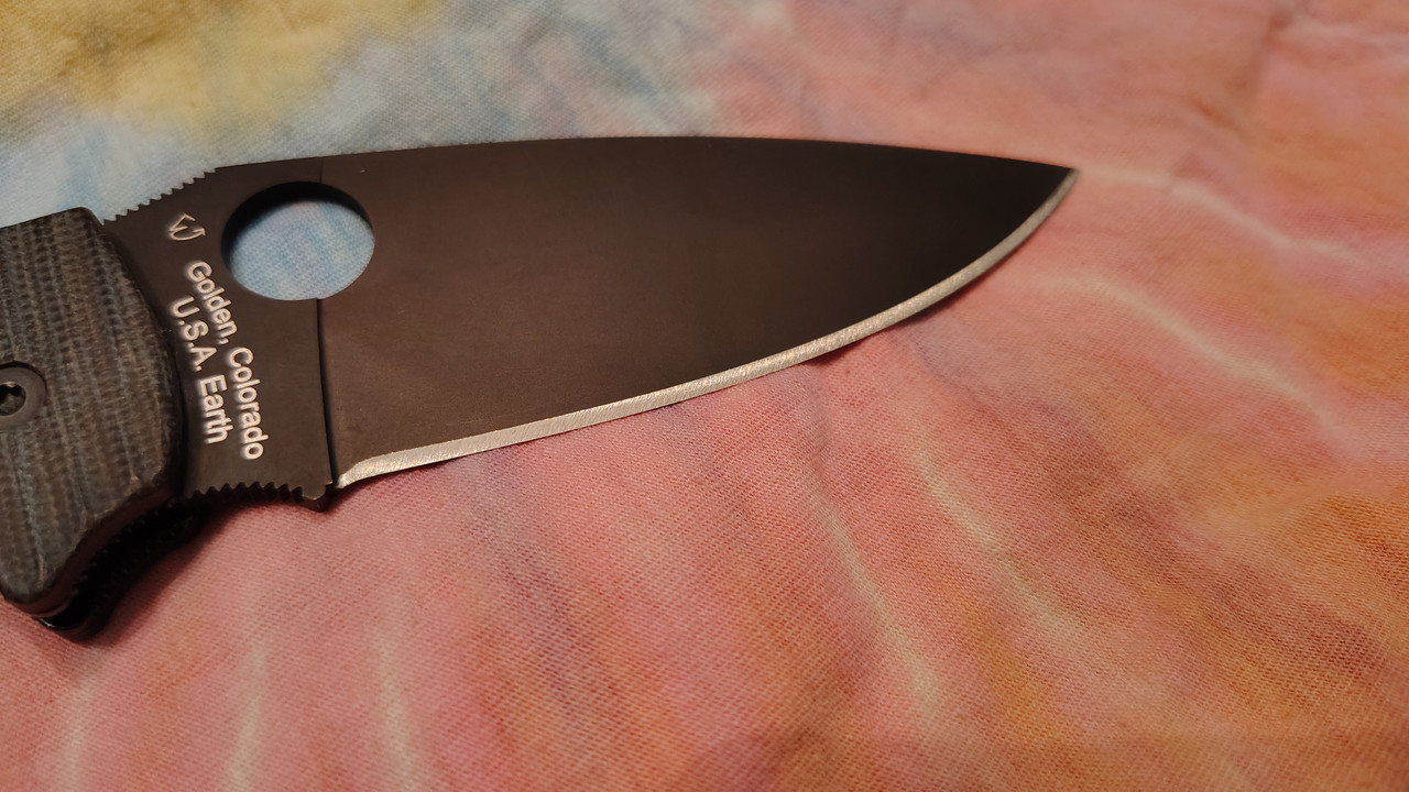
Also, a pretty good unintended example of the convexity of free-handed bevels going on with this one. Usually I hold a bit steadier in terms of going lower than my intended angle, but I was focusing on not trying to overshoot the apex too much this time. But it's a good example of how an edge that looks like it's about 10dps by the bevel height is just fairly convexed and is actually >=15dps.
I tested one edge and can see both sides are primarily 15dps, but there's the faintest little hint of the reflection from the 15-17 lines on one side, and from 15-16 on the other. But it's those faint lines that micro-bevels form so I know that's the true geometry and not just aberrant diffusion/scatter of the beam. Especially because they appear like that from the intended micro-bevels too.
PXL_20250818_015100607~2.jpg
Here you can see where the micro bevels start at the 15 degree lines. On one side it goes from 15-26 and the other 15-24. I used a 20 degree wedge so 20 + ~2.5 (for the blade grind) should have been 22.5, but I over-shot by 1.5 and 3.5 degrees respectively. It's a lot harder to nail the desired angle within +/- 2 degrees on a tiny little micro-bevel than on a huge bevel where I am putting most of the deviation into the shoulder.
PXL_20250818_073818579~3.jpg
PXL_20250818_073823661~3.jpg
I'm calling it a 33 degree apex vs a 50 degree apex, but not sure how valuable the numbers I would get with this would even be so I only did 3 cuts each for now. No sense in doing a lot more if my whole test methodology needs revision.
Unintended 33 degree apex on an intended 30 degree edge:
1st cut: 1.490kg
2nd cut: 1.183kg
3rd cur: 1.474kg
Avg: 1.382kg
Intended 50 degree micro-bevel apex on an intended 30 degree edge:
1st cut:1.461kg
2nd cut: 1.750kg
3rd cut: 1.675kg
Avg: 1.629kg
The average force increase necessary for the 50 degree micro-bevel is .247kg. Out of a maximum value of 1.750kg and a total spread of .567kg. That 1.183kg value might be an outlier, but even if I adjusted it up to 1.483kg to be more consistent with the full set, that would still be a .147kg increase in the average force over a spread of .288kg. With an average force of 1.55kg (regardless of that outlier) over either set of data, then the increase in average force over both sets is about 9.4% of the total average force to cut the Q-tip with either geometry.
What do you think of such a test and assessment of the values?
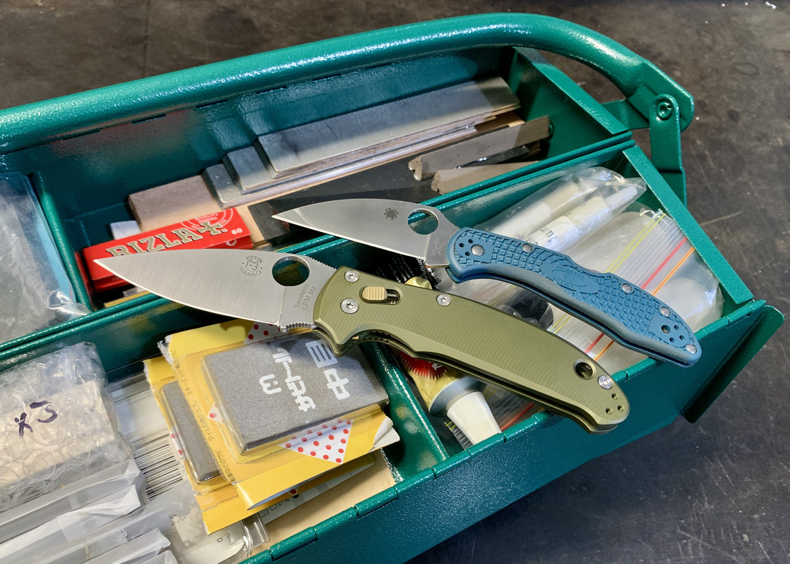
Also just for extra illustration purposes this is the micro-bevel in question. It looks larger in the picture than under a loupe somehow. Especially near the heel. The marker is where I am testing the geometry and cutting.
PXL_20250818_074550196~2.jpg
PXL_20250818_074610651~2.jpg
vivi wrote: ↑Sun Aug 17, 2025 7:45 pm
I've tried both a home made BESS style tester (V notched block of wood with small nails on either side and thread looped over the notch) and kitchen scales.
In my experience the former is better for measuring raw apex sharpness, while the latter is better for showing the differences between overall geometry.
I was able to cut carrots and apples with
1/4 the force with a stock Pacific Salt VS a reprofiled edge bevel one, for example.
The difference is even more dramatic if you thin the full primary grind and not just the bevel, as shawn has always pointed out in the past.
Yeah, I was trying to find something to test the whole bevel instead of just the apex, but also not the primary blade grind. However I'm thinking that removing the blade grind from the test probably makes the difference harder to observe as you say.
I'm trying to think of a different tear medium to test both the bevel and blade. Not sure about carrots, they seem like they'd be kind of inconsistent? I was thinking about just the standard rope, though perhaps nylon instead of a natural fiber. Otherwise I was also thinking about pencil erasers or something like that. Something that would really engage the blade surface and put friction into the equation to see if that amplifies the observable effect of differences are the edge.
Thanks!
I haven't been able to follow up with any more actual testing, but I have been thinking about things to test and how to further test them.
I was going over some of Larrin's older articles...
https://knifesteelnerds.com/2018/06/18/ ... retention/
https://knifesteelnerds.com/2018/08/06/ ... g-ability/
They had me wondering more about the relationship between the apex radius width and cutting ability. If I understand his conclusions correctly, edge angle controls cutting ability more than any other factor, and that an acute edge had greater cutting ability than an obtuse edge, even if the obtuse edge's apex remains narrower than the apex of the acute edge.
I am thinking about doing something like cutting up a ton of cardboard, and in specific intervals taking the BESS score and plotting that out. I have done that in the past, but I think this time around I could do it in conjunct with the Q tip test. Because I think that as in the articles, BESS is really going to be a factor of the apex radius width, but the force in the Q tip test will be a factor of both the apex radius as well as the rest of the edge geometry displacing the material.
I think the first obvious test I would run is to take a 30 degree bevel, run it through cardboard and plot both the BESS and Q-tip cut-force (I may be too modest to refer to it as the Mage score lol) and then do the same with a 30 degree bevel with a micro-bevel and see what differences shake out.
But I will need to get a new BESE tester. The one I have is one of those ancient prototype ones...
It's just far too temperamental. I always seem to get wildly different readings from one reading to the other, because there's just so much variation on tensioning the thread I think. I been wanting to get one of the new ones to use the clips with. Seems like it would be a lot more accurate and also not nearly as much of a hassle. Spooling up the thread, loading the weight, etc. gets really tedious when plotting it out over thousands of cuts.
It's pretty disappointing though seeing that their "home model" only has 25 gram resolution. I wonder what the max capacity is as well. It would be nice to be able to use it to measure the peak force on the Q tip test too.
vivi wrote: ↑Mon Aug 18, 2025 9:33 pm
to be fair 50dps microbevel is pretty extreme. I don't run an apex at that thick of an angle on my 28" chopping axe
the performance differential would be a lot smaller with, say, a 32-35dps micro.
Yeah I was aiming for closer to 45. But also at least the exaggerated difference helped show some amount of difference. Hard to really draw conclusions on the amount of measurements I took, but the amount of force increase wasn't really that much even with such a big bevel, so I think you're right. I plan to test micro-bevels with much less contrast to the main bevel.
vivi wrote: ↑Mon Aug 18, 2025 9:33 pm
so micros are a good balance for me. cutting performance, extremely fast touch-ups, edge toughness, corrosion resistance....many factors at play.
I am sort of just making this an academic pursuit to see if I can find a way to use micro-bevels in a way that reduces the increase of apex radius width when cutting through more obtuse geometry, but that doesn't reduce cutting ability are the same time. Because my intuition is telling me that the reasons why a more obtuse edge bevel would reduce cutting ability should reduce in proportion to the size of the bevel faces. Things like the friction and material displacement should be minimized the smaller the bevel faces are, but also allow the apex to preserve a narrower apex radius for longer. Basically the best of both worlds. Though, as Shawn was saying that he's observed micro-bevel edges basically acting like they would if they were a whole V bevel if that geometry so I may be overly optimistic, but my hopes are that extremely small micro-bevels will accomplish this.
Speaking of academic pursuit..
Can anyone explain these graphs from those articles to me?


It's said that, "A typical test for a plain edge steel knife is 60 cuts with 50N load at 50 mm/s," but what does the cut length and the 50 mm/s reference here? Is it the length and rate of the slicing stroke or the depth of the cut into the stack of cards?
If it's length of the stroke, how is that controlled? If you look at the line for the 20 degree edge beginning at cut 20 there's a pretty interesting fluctuation between 10 and 20 that would seem like it would rule out that it pertains to the length of the slice since that would mean the blade was basically being sawed back and forth in increasingly short strokes.
So then it must be the depth of the cut into the card stack, but then doesn't it just correspond to the TCC graph too since cards are 1mm?
Just wanting to make sure I am reading all that right.


 [/url]